
Last modified on September 18th, 2024 at 3:36 pm
Yes, our cameras meet OOOOa, OOOOb, OOOOc, and Appendix K regulation standards.
These regulation standards define the minimum detection and visualization capability needed for optical gas imaging cameras. We would like to give insight to our testing process to verify that our OGI cameras meet these standards.
OOOOa was the original regulation which was set at 60g per hour with a mixture of 50% methane and 50% propane. That equates to about 10,000 parts per million(PPM). In the new regulations the EPA decided to focus on three individual control gases. The three control gases for the new oil and gas regulations are methane, propane, and butane. Methane requirements for visualization will be 19 grams per hour, 22 grams per hour for propane and 29 grams per hour for butane.
The Ventus OGI can visualize All three gases and 19 other hydrocarbon gasses
It will not discern the type of gas it is. Through the camera all gasses will look the same. Generally, the customer knows which gases are flowing through their systems and through which pipeline or unit. If there’s a leak in this area, they know with high certainty which gas is leaking. To see a full list of gasses head to the Ventus OGI Product page.
Appendix K is now requiring an Operating Envelope
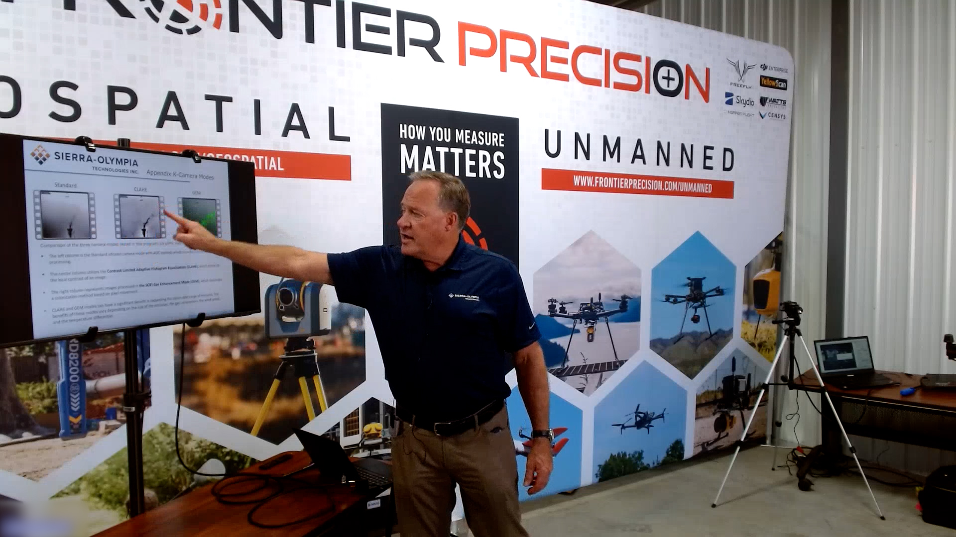
Appendix K is now requiring that either the end user, operator, manufacturers like Sierra-Olympia, or service companies establish an operating index and operating envelope. When you’re using an OGI camera, especially if you’re going to use it as the alternate to method 21, using sniffers, you must to validate the tests and data being collected. When we went through our most recent testing to validate for appendix k we decided to follow what the EPA was doing and kind of show people what this might look like. To our knowledge we are the very first company in the United States to do this. We established characteristics of OGI performance, performance audits, necessary supplies, site facility inspections, record keeping and field conditions.
OGI Performance Summary
Document evidence the OGI camera performed as stated in the Operating Enveloper definition
Field Condition Validation
Define whats needed from environmental data
Performance Audits
Evidence showing that the Operating Envelope was not exceeded.
OPERATING ENVELOPE
Record Keeping
Documented evidence the inspection was within the Operating Envelope
Necessary Supplies
Helps to define what is needed for an inspection
Site/Facility Inspection Requirements, Monitoring Plan, Training Plan
Essential elements of the monitoring plan
We established these test parameters and operating envelope, so we can validate data that our camera can meet the leak detection and repair(LDAR) inspection requirements. Many companies are not doing the testing to this high of level. They are only trying to find the leak and fix the leak, not trying to quantify the size of the leak. This is because if an auditor comes and finds a leak before you do, they will start fining you. They will start the fine from the last day their inspection was performed. If that was a year ago, the fine starts from a year ago because they will assume it has been leaking that entire time. That’s why the operators can be assessed large fines in the tens, hundreds potentially in the millions dollars in some cases.
In the Appendix K validation testing using the Ventus OGI these operating conditions were used. Wind speeds from 0 to 10m/s, (0-22mph) . Distances from 2 to 25m, (6ft-82ft) and Delta T’s from 1 – 15°C . In addition, two different lenses were used , a 25mm and 50mm lens with three different operating modes, i.e. AGC (Std.), CLAHE (Contrast Limited Adaptive Histogram Equalization) and GEM (Gas Enhancement Mode) modes different operating camera modes. Lastly, 3 different digital zoom modes were used, i.e, 2X, 4X and 8X.. Wind speeds from 0 to 10m/s, (0-22mph) . Distances from 2 to 25m, (6ft-82ft) and Delta T’s from 1 – 15°C . In addition, two different lenses were used , a 25mm and 50mm lens with three different operating modes, i.e. AGC (Std.), CLAHE (Contrast Limited Adaptive Histogram Equalization) and GEM (Gas Enhancement Mode) modes different operating camera modes. Lastly, 3 different digital zoom modes were used, i.e, 2X, 4X and 8X.
You have to establish how and when you’re going to be able to use that camera and successfully. The purpose is to be able to find a 22g/hr methane leak. To test the Ventus OGI we created a whole bunch of videos, sent them out to a bunch of different senior operators, and they’d grade the observed ability of the leak and the probability of detection. That’s what we call an observability and probability of detection index. Which means from a senior operator to a junior operator, how likely it is that all of these people agree that they can see the leak. Then what created hundreds of graphs and plots, about changing the distance, wind speed, and deltaT. The end result of that came out exactly what we thought it was going to be.
Wind Speed
0 – 10 m/s
Digital Zoom
2X, 4X, 8X
Distance
0 to 25m
TESTING PARAMETERS
Camera Mode
Standard, CLAHE, GEM
Delta-T
0°C – 15°C
Lenses
25mm and 50mm
All of the parameters can have an effect
How far away you are monitoring from will play a role in the leaks that you can see. We’ve run test that have detected gasses at 1,000ft but those leaks are in kg’s/hr not grams/hr.
One of the easiest and fastest ways for validated our Ventus OGI camera has been to use either Porta Gas bottles with a 50%/50% mixture of methane and propane. In addition we often use propane cylinders used for grills or camping On the Porta Gas cylinders we use calibrated regulators set at 60grams/hr or 6 grams/hr. For testing purposes the camera operator can set the bottle out to a distance of 6-10ft to start with and continue to increase the distance between where the camera is being operated the bottle or cylinder is located until you can no longer see the gas leak. Thus, on that given day, under the current climate conditions of wind, overcast, sunny or partly sunny, or in a light rain, the camera operator can establish what his operating envelope is for that part of the day. The EPA and your air quality boards are asking facilities or manufactures to define this criteria so they know when the operator does an LDAR inspection, the operator knows what the limitations of their equipment is. This goes for equipment including aerial, handheld, fixed cameras doing continuous monitoring, or any use of optical gas imaging.
The general trends that we found as the temperature differential increases, the observability increases. As wind speed increases, the observable decreases because it disperses the gas. As distance increases, observability decreases. We also found you can correct for certain advantages by using longer, narrower field of view or more telephoto optics. If you’re just using the one control, meaning a 25mm lens, these rules would exist at some degree, but you can always affect these by changing operating modes.
General Trends
- As Temperature differential increase, the observability decreases
- As wind speed increases, observability decreases
- As distance increases, observability decreases
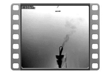
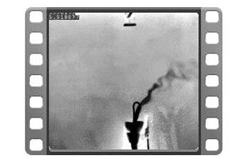
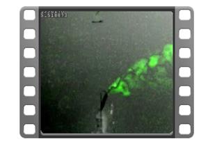
Above you can see examples of the standard AGC mode, CLAHE mode, and GEM mode. Take notice of how CLAHE can looks a lot better that standard mode through use of contrast and edge refinement. When you use the GEM mode, the Gas Enhancement Mode, it’s even more visible through coloring the gas. What we found is that GEM mode in many cases, allowed us to visualize that same leak twice as far. To learn more about the Ventus OGI and how it’s leading the industry standards please visit the product page.
640 x 512
MWIR